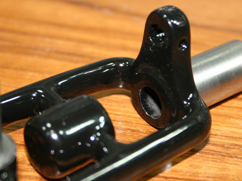
Bottom
view of the Friction
Roll mounting bracket.

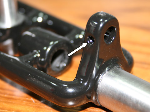
The same mounting
bracket from different view-point. The arrow points
to the place where locking screw will be place. The screw
will lock the shaft of the "Friction Roll" in the desired position.

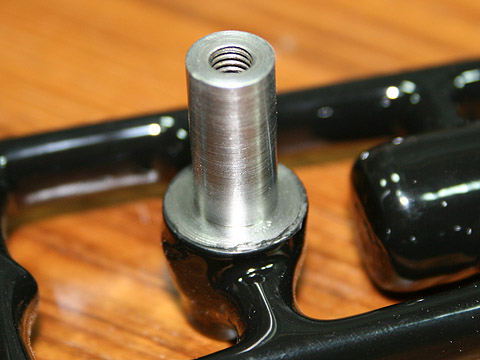
Here is the shaft for main
gear. It is an integral part of the frame casting and
machined to final shape. Polished surface will ensure smooth turning
of the gear. The tread in the center of the shaft is
provided for gear locking screw.

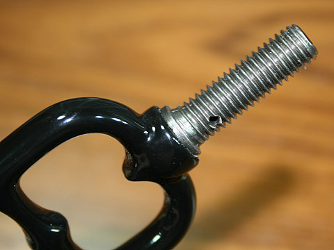
This is the handle mounting threaded rod. This rod is cast as an
integral part of the frame, the tenon for a handle ferrule is machined
and the thread is cut. As we will see on the next page,
this is an important detail.