

The shell of the chuck has patent information stamped on the
smooth bend. The base of the chuck holds jaws in machined
grooves.
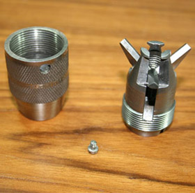
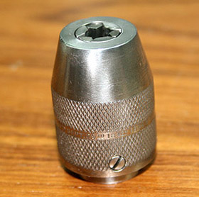
It is a simple and effective construction.
The Friction Roll
Millers Falls catalog for 1903 describes this part of the drill
in one sentence - "It has cut gears and adjustable friction roll
to prevent gears from springing out of engagement."
The
function of the Friction Roll is to control the main gear and
single pinion gear in proper alignment and ensure smooth
rotation.
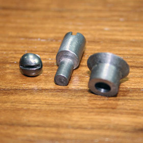
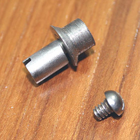
There are three parts to this device: a cylinder with
machined off-set shaft, a flanged roller wheel mounted on the
shaft, and a locking screw to hold the cylinder in the mounting
bracket.
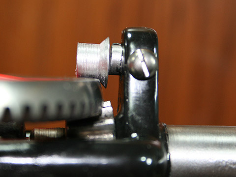
When installed, the wheel rides on the shaft and by lightly
touching the rim of the gear, it controls the thrust that tends to
push the teeth of the pinion and the gear out of engagement.
The gap between the roller and gear's rim is adjusted by turning
the shaft cylinder.
Since the shaft is not in the center
of the cylinder, it will move the wheel further or closer to the
gear's rim. The locking screw is used to do just that -
lock the position of the cylinder in the desired place after
adjustment of the gap is achieved.