Drill No. 2A Transitional Construction Elements
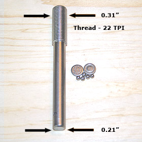
This variation in ball numbers was dictated by different diameter of the spindle
and spindle seat used in the drills over the years. The
spindle diameter on No. 2-1938 is 0.21875". The No. 2A -
Transitional returned to spindle diameter of 0.25", used on models
from 1895 up to 1920. With larger diameter of the spindle
the ball bearing in No.2A Transitional was also changed to one
ball without races and then carried forward to No. 2A - Zamak
and later models.

Spindle and Ball Bearing on No. 2 - 1938 |
|

Spindle and Ball Bearing on No. 2A -
Transitional |
The change in the spindle diameter and thread size required change in
a chuck as
well. The chuck used on 1938 No. 2 drill was designed and
patented by Henry A. Ryther, an employee of Millers Falls Co.

The patent receive No. 1,470,197 on October 9, 1923.
It was one of the best, if not the best,
chuck designs of the era.
The same chuck was used on No. 2A Transitional drill
and continued on the later, 1957 version. Obviously, the
opening was changed to the 0.25 inch and the thread to 24
TPI.

On the left - Chuck from No. 2 - 1938 drill. On the right
- chuck from
the No. 2A Transitional drill.

Chuck from the No. 2A Transitional drill.
Another significant change occurred in the main handle mounting
parts. However, this change was initiated in later version
of 1938 model, most likely in early 1950s. The original 1938 No. 2
hand drill continued with
concept used previously on drills from models released between 1903
and 1935.
These
were the drills that employed a friction roller at the
top of
the single pinion and main gear.

All these drills were designed with a threaded stem at the end
of the frame. It served as a mounting screw for main handle. Although the
opening in main handle was not threaded, it was screwed on using
moderate force and pinned to the stem through the handle's ferrule.
With 1938 model the frame was redesigned to accommodate second
pinion. The system had to be created to
provide a way to secure the pinion and main handle
in place of previous threaded bolt.